Intel® Volume Management Device (Intel® VMD) RAID Management Controller for Intel® Virtual RAID on CPU (Intel® VROC)
Intel® Volume Management Device (Intel® VMD) RAID Management Controller for Intel® Virtual RAID on CPU (Intel® VROC)Category:Article ID:000101179Environment:Intel® VROC for Windows*Date:12/22/25 With the introduction of the Intel® Xeon® Scalable processors family, one of the key features included is the Intel® Volume Management Device (Intel® VMD) technology. Intel® VMD is an integrated PCIe endpoint within the CPU root complex. The class code for the Intel® VMD device is a RAID controller. Intel® VMD driver support is provided with the Intel® Virtual RAID on CPU (Intel® VROC) package and includes the following:
Intel® VROC (VMD NVMe* RAID) Features The Intel® VMD technology is one of the key features of the Intel® VROC (VMD NVMe* RAID) sub-product. To learn about other key features of this Intel® VROC sub-product, refer to Key Features of Intel® Virtual RAID on CPU (Intel® VROC) VMD NVMe* RAID for Windows*. Each Intel® Xeon® Scalable processor family with Intel® VMD 2.0 technology provides up to 64 PCIe lanes which is subdivided into four domains. Plus one domain for the Platform Controller Hub (PCH). Those with Intel® VMD 1.0 technology provides up to 48 PCIe lanes which is subdivided into three domains. Each Intel® VMD domain manages x16 lanes. Intel® VMD can be turned on/off on x4 or x2 (x2 starting with Intel® VROC 8.6) lane granularity and supports either NVMe* Solid-State Drive (SSD) devices or PCIe switch devices. Intel® VMD is also designed to support the following types of NVMe* drives:
Multiple Intel® VMD ControllersEach Intel® Xeon® Scalable processors family contains at least three Intel® VMD controllers. The number of Intel® VMD controllers seen is dependent on the processor being used. Check the respective Intel® Xeon® Scalable processor family documentation, for a given SKU, for the specific Intel® VMD controller count. 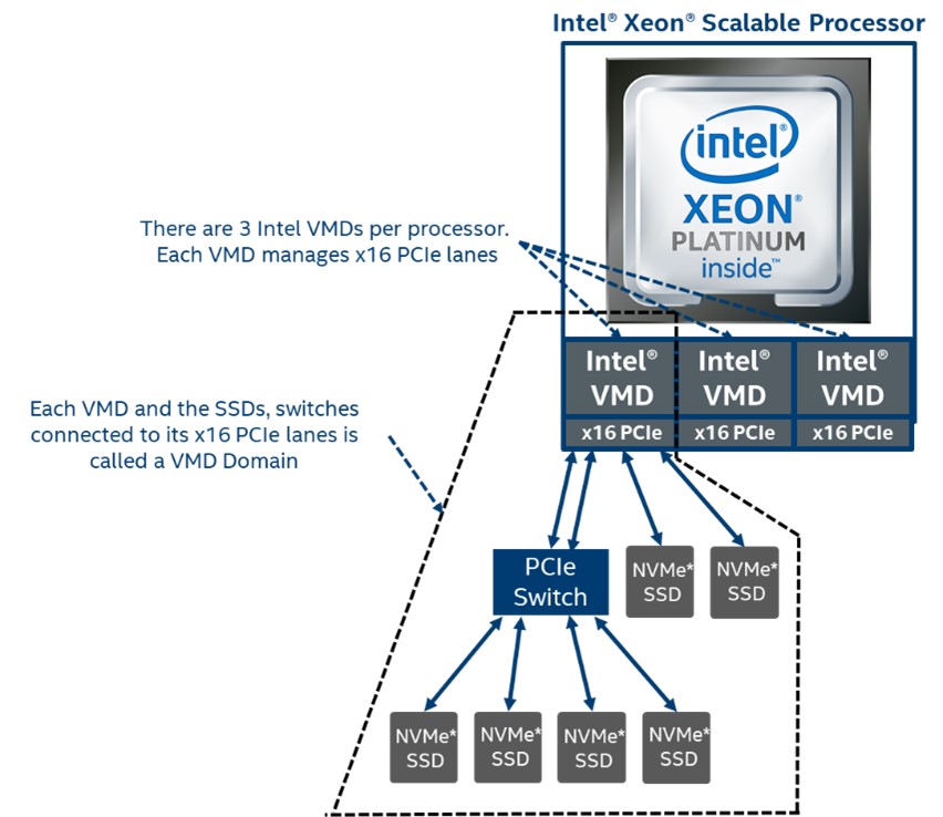 Note The ability to turn the Intel® VMD domains on/off is intended for supporting configurations that require utilizing non-NVMe SSD devices (e.g. a Graphics Add-In-Card). This feature is not intended, nor does the VROC product support, a configuration where the Intel® VMD controller has one or more domains disabled (off) with NVMe SSDs connected (e.g. used as a system boot drive) while the remaining domains are enabled (on) and managed by VROC. The VROC family of products requires that Intel® VMD be fully enabled when only NVMe SSDs are attached. And that the on/off domain granularity be used only when non-NVMe SSDs are being used. Intel® VMD Method of LED ManagementBackplane LED management is a critical part of enterprise RAID management. Intel® VMD provides a mechanism to support LED management on Intel® Xeon® Scalable processor family platforms. The mechanism utilizes repurposed two of the PCIe Slot Control Registers (Power Indicator Control and Attention Indicator Control of the Slot Control register) to support IBPI blink patterns defined in the SFF-8489 standard. LED management outside of a supported backplane environment is not supported. For details on how to utilize and/or customize the LED management behavior, refer to Intel® Virtual RAID on CPU (Intel® VROC) LED Management Capabilities for Windows*. Intel® VMD Error ManagementIntel® VMD technology handles Advanced Error Reporting (AER) and functions as a crash dump and hibernate target within the Windows* operating system, therefore providing protection to the rest of the PCIe bus, preventing whole system shut down. Upon receiving an interrupt at MSI-X 0 for each root port, Intel® VMD uses a sophisticated algorithm to determine the precise device to apply error handling-based severity. The actions taken are specific to the error on the device and preserve the remaining ecosystem. The Intel® VMD controller will handle the errors as follows. The list of errors handled are listed in the table below.
These messages will be seen in the Windows* System Event Viewer environment. The Event ID that will signify one of these conditions has occurred is 11. Gather this information and provide it to your Intel® VROC representative for analysis. Machine Check Architecture (MCA) If IIO MCA is enabled on the platform, this will supersede all error reporting, even when Intel® VMD is enabled. As a result, Intel® VMD error reporting may not properly handle errors seen on Intel® VMD root ports. To help ensure that these errors are properly handled, consult your platform BIOS user guide to set IIO MCA to disabled.
Intel® VMD EnablingThese instructions will explain how to enable Intel® VMD in an Intel® Customer Reference Board (CRB). Refer to the instructions provided by the user’s platform BIOS vendor because those instructions will most likely be different from these instructions.
Refer to the user’s platform BIOS manufacturer documentation for a complete list of options that can be configured. 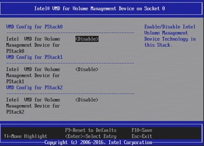 Intel® VMD Surprise Hot-Plug of NVMe* DevicesOn Intel® Xeon® Scalable processor family platforms with supported hot-plug backplanes, when Intel® VMD is enabled surprise insertion and removal of NVMe* drives is expected to work just like SATA drives surprise insertion and removal. Drives will automatically appear or disappear without requiring manual scan in the Device Manager. Surprise hot-plug is only supported for U.2 form factor NVMe* drives; other form factor (AIC, M.2) SSDs do not support surprise hot-plug. When Intel® VMD is enabled, surprise insertion and removal of NVMe* drives is isolated from the PCIe bus and managed by Intel® VMD. The Intel® VROC (VMD NVMe* RAID) driver takes appropriate action on NVMe* SSD device changes based on SFF-8639 interface (U.2 form factor only). This includes surprise insertion/removal of 2.5” form factor devices in the operating system runtime environment. |